Mechanical Design
|
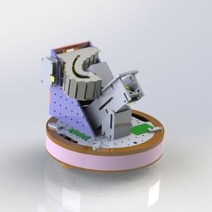
Teddy's mechanical design was fairly bare bones to keep the cost and complexity down. The main mechanical subsystems included a chassis, drive train, shooter, and loader. All of the circuitry, the TIVA, and power components were integrated into the mechanical support structure.
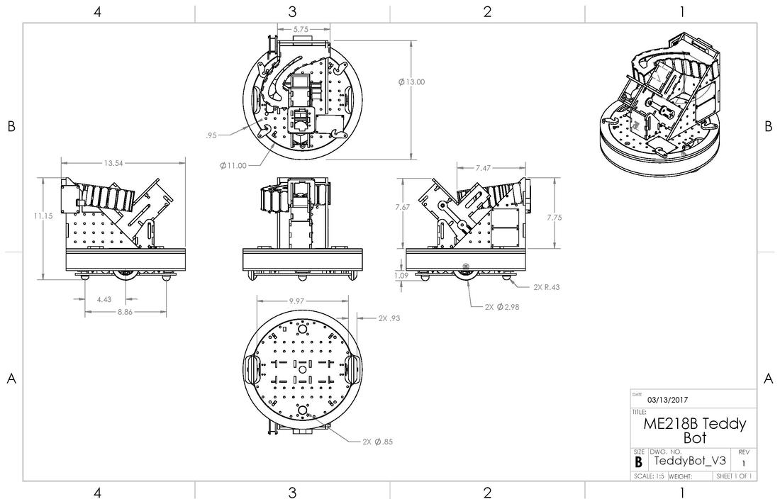
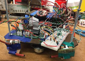
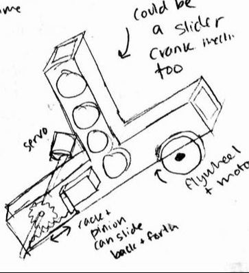
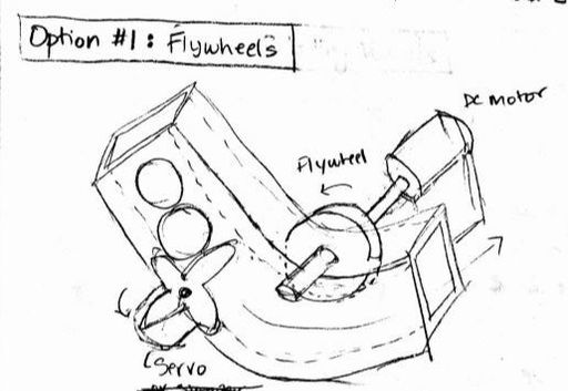
The shooter ejection mechanism was one unique aspect of our design. A servo-driven crank-slider pushed the balls into a flywheel, allowing for a consistent feed rate, in order to achieve high-repeatability shots. Overall, packaging all of the electronics was a big challenge for our design. Our placement of wiring and circuit boards, especially on the upper level of the bot, was not ideal. For our next project, we aim to be much more conscious of how many circuit boards we will have, where they will be mounted, and account for dense wire routing. Below is a basic mechanical sketch showing relative scale. |
|
Chassis
The main chassis of our robot was built with laser-cut Duron paneling.
Initial Threaded Rod Three-Level Chassis
|
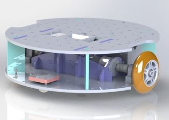
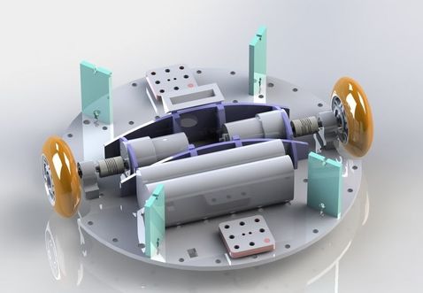
Render of Final Duron Support Chassis
|
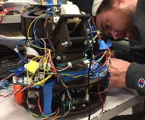
John installing motor components to the final chassis
|
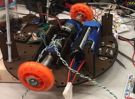
Drive Train
The drive train consisted of two brushed DC electric motors, helical shaft couplers, pillow blocks, and skate wheels. Teddy was powered from two 7.2V NiMH batteries that we located near the drive wheels for increased traction on the playing field. Small plastic ball casters in the front and the rear provided the third necessary point of contact with the floor. We initially started with a suspension on the rear caster to prevent the two casters from lifting one of the wheels off the ground. For simplicity, our final solution was to remove the suspension and raise the rear caster 4mm off the ground, a large enough spacing to ensure only 3 points of contact with the field surface at any given time.
|
|
Ball Shooter
|
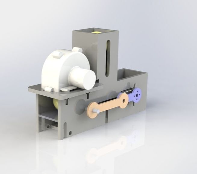
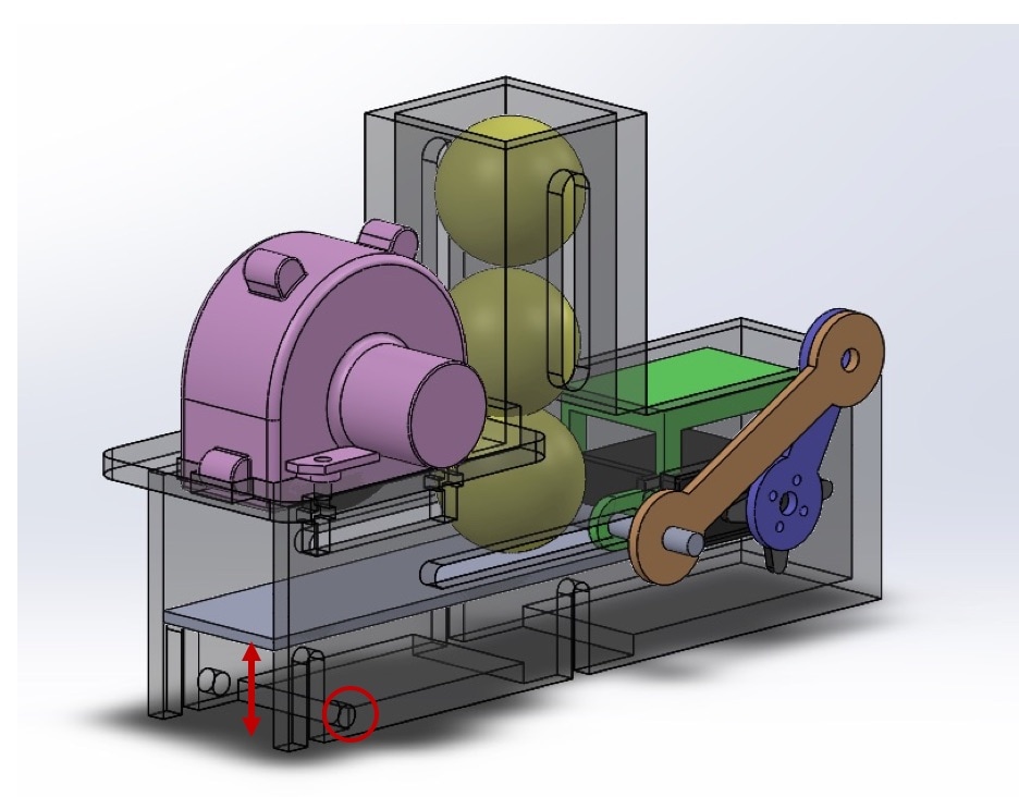
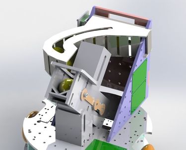
The ball shooter employs a servo and a flywheel/motor kit (pink). The servo is attached to the linkage in purple. As the servo rotates, the blue (or orange) linkage is pushed&pulled within a slot in the housing, and therefore a slider within the shooter housing (green) is as well. The slider moves past the column of balls, allowing one ball to enter the horizontal part of the housing and pushing the ball through to the flywheel.
|
|
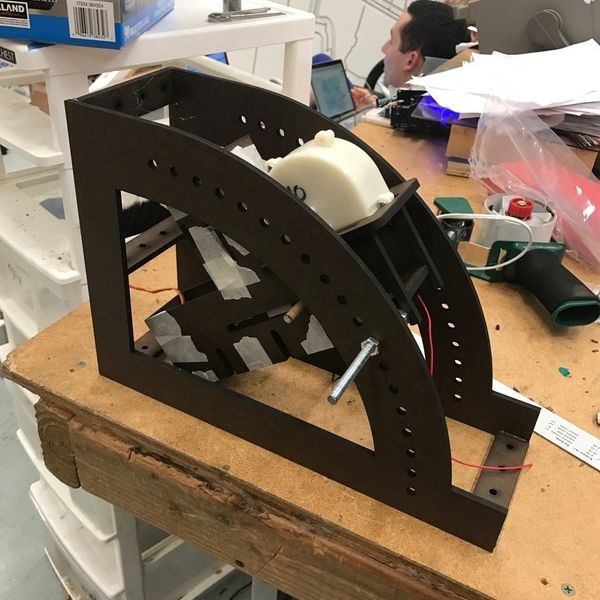
The bottom platform (grey) is adjustable (via a bolt that can move up and down within the slots shown to the right), allowing for experimentation of the interference between the ball and the flywheel. In addition, the ball shooter can be threaded onto a rod (via the through hole circled to the right), which fit into an assembly that allows for adjusting the angle of the shooter (shown below). With this assembly, we could determine the ideal angle of the shooter in order to get precise and accurate shots.
We went through a few iterations of ball shooters in order to get to this final design. This design worked really well in terms of pushing the ball consistently through to the flywheel. However, the biggest problem was "tolerancing" the slider (green) within the housing accurately. Because it was too short, the next ball up in the column would get jammed as the slider moved past the column. Click here to see the above video. |
|
|
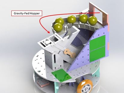
Ball Loading
To reload, Teddy captured more construction materials through a port on his back. Gravity drew the balls down toward the shooter along a curved staging area designed to allow balls the drop into the shooter whenever another one was needed.
|
|
