Electrical Design
We developed a variety of signal conditioning circuits for different sensors . All of our circuits were modular so we could easily replace the ICs if any of them accidentally got burned, which is bound to happen when someone accidentally connects 14V to all of the 5V circuits. Our wire follow circuits were very finicky, but we made them more robust when we fixed our molexing and added a high pass filter to filter out the check in station frequencies.
Tiva Pinout
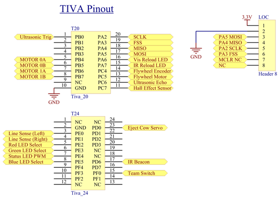
We comfortably fit all of the functionality required for the bot within the pin limitations of the TIVA Launchpad. The pinout diagram at right shows the functionality of the pins in use. Due to hardware issues with the drive wheel encoders, we removed closed loop control and saved several I/O pins formerly dedicated to the encoders. The tightest I/O pin constraints were PWM ports and timer pins, both of which require us to iterate through several possible alternate function mux settings before we found a solution.
| Tiva_Pinout.pdf |
Motor Drive
To power the drive motors, we used two pre-built H-bridges with TLE-5206 chips.
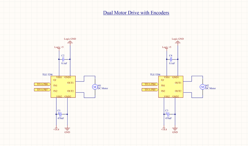
| Motor_Drive_Circuits.pdf |
Flywheel Motor & Loader Servo
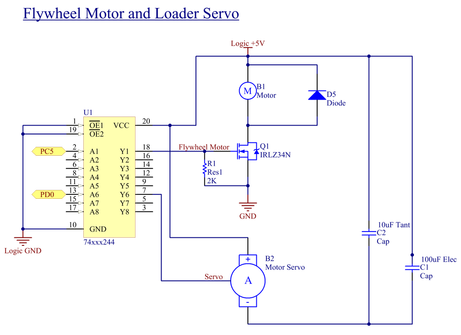
Our shooter was designed around a flywheel containing a small brushed DC motor and a ball-ejectoring crank-slider linkage powered by a 180-degree servo.
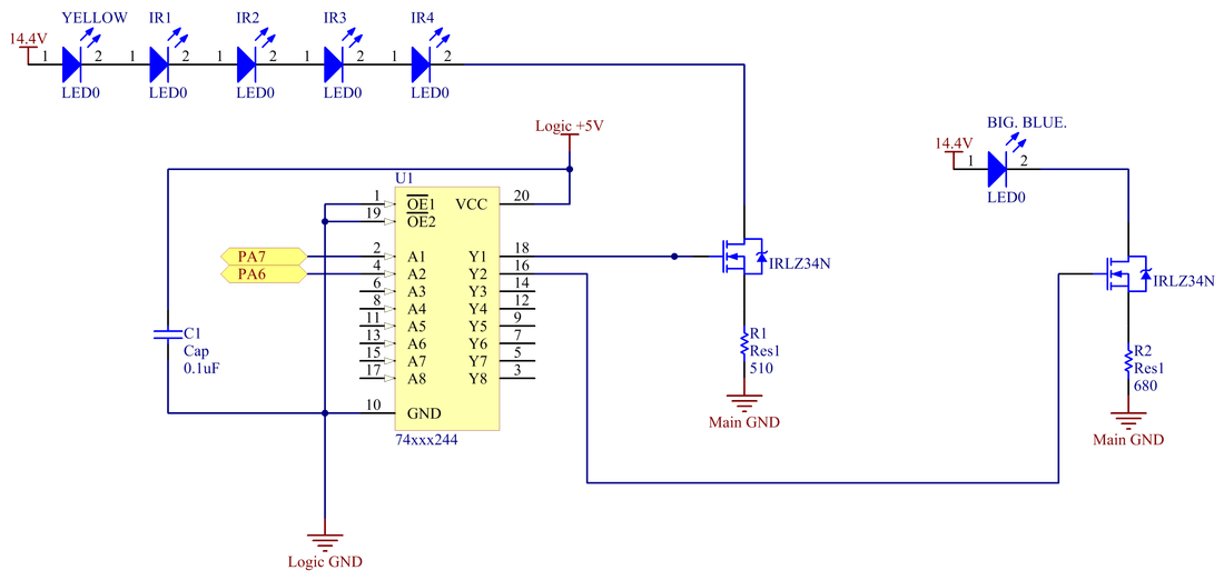
To raise both the servo PWM and the motor drive signals from the TIVA 0 to 3.3V to a desired 0 to 5V range, we passed the signals through a TI 74HCT244 non-inverting buffer.
To drive the flywheel motor, we used a simple IRLZ34N power MOSFET paired with a flyback resistor. To prevent input floating on the IRLZ, we added a pull-down resister on the output.
The servo control scheme used the standard 50Hz input signal with a duty period of 1 to 2ms. The 1ms time corresponded to the extreme position in on direction, and the 2ms in the other.
| Flywheel_Motor_and_Servo.pdf |
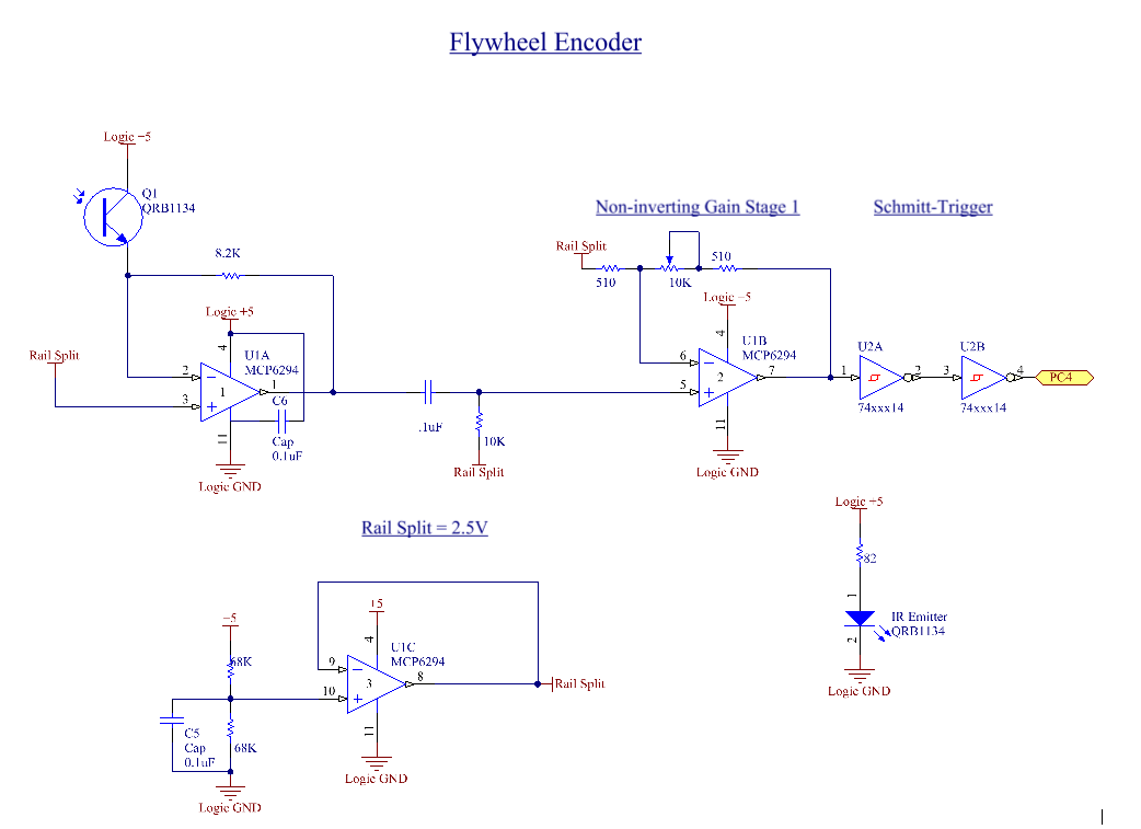
Flywheel Encoder
For precised control of our flywheel, we implemented basic PI closed loop control. We mounted a Fairchild QRB1134 IR phototransistor sensor to our flywheel and conditioned the signal with the circuit below to measure the rotation speed of the flywheel.
The circuit began with a transresistive circuit followed by an AC-coupling high-pass filter. To amplify the AC signal, we amplified the signal with a non-inverting gain stage with a potentiometer-controlled gain of approximately 21. Finally, to first create sharp edges and then to rectify it, we passed the signal through two Schmitt-Triggers on a TI-74HCT14. A railsplitter circuit provided a clean reference voltage at 2.5V throughout the signal conditioning circuit.
The encoder and signal conditioning yielded a very good speed measurement, allowing for smooth control of the motor.
| flywheel_encoder.pdf |
Line Sensing
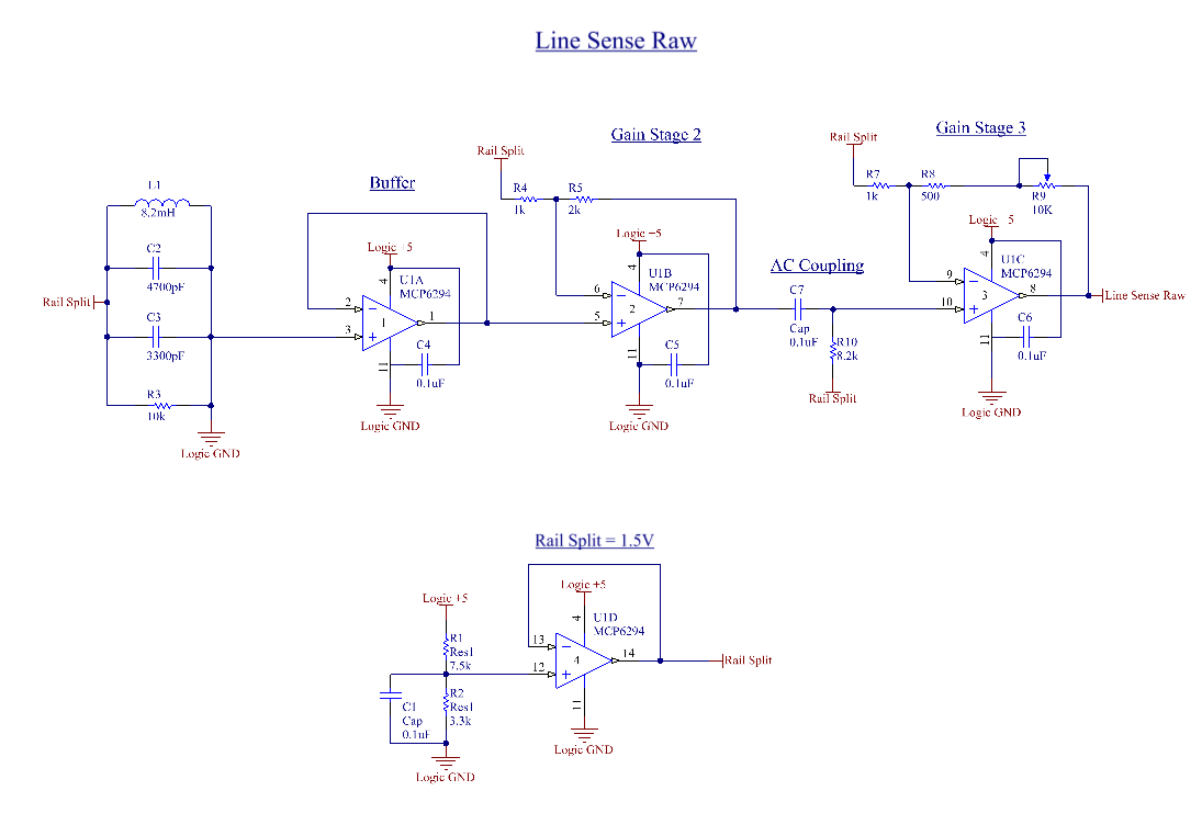
The Line sensing circuit consisted of a tank circuit tuned to resonate at roughly 21 kHz. The 10k resistor in parallel with the LC circuit effectively de-tuned the circuit so that a wide range of frequencies would trigger resonance in the circuit. Two of these circuits were mounted on the robot and fed into the Tiva ADC. The difference in amplitude between this two circuits gave an effective "error" from being centered over the path wire.
The output of the tank circuit was buffered before being amplified twice. Unlike other circuits which we biased around 2.5V (the center of the 0-5V range) this circuit is biased at 1.5V. This was done to provide a wider range of valid voltage measurements at the Tiva ADC which can read values from 0-3.3V. The potentiometer on the final gain stage allowed for tuning of the circuit after it was mounted on the robot. This was important because the circuits needed to be tuned for small differences in mounting in part tolerances. This let the robot stay centered over the wire.
The output of the tank circuit was buffered before being amplified twice. Unlike other circuits which we biased around 2.5V (the center of the 0-5V range) this circuit is biased at 1.5V. This was done to provide a wider range of valid voltage measurements at the Tiva ADC which can read values from 0-3.3V. The potentiometer on the final gain stage allowed for tuning of the circuit after it was mounted on the robot. This was important because the circuits needed to be tuned for small differences in mounting in part tolerances. This let the robot stay centered over the wire.
| line_sense_raw.pdf |
Line Sensing Filter
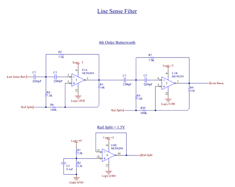
While the tank circuit shown above worked very well to pick up the current carrying wire, staging areas were also sensed which negatively affected driving in those areas. To mitigate this we built this high-pass filtering circuit to attenuate the lower frequency staging area signals. Because the highest frequency of the staging areas was relatively close to the the frequency of the path wire, a high-order filter was required. A 4th order Butterworth filter did an excellent job of removing all signal from the staging areas while leaving the amplitude of the path wire signal unaffected. This greatly improved driving at relatively little effort in building.
| line_sense_filter.pdf |
Beacon Sensing
The IR beacon sensor consisted of a trans-resistive circuit which is amplified through two gain stages. The first stage amplifies the signal by roughly 10x and the second stage is adjustable using the potentiometer from 10x - 30x. This gave us flexibility to tune the circuit to avoid excess saturation for closer beacons while still capturing important IR signals on the field. While estimates of these values and calculations were integral to this circuits design. The ability to tune while on the field and testing was indispensable in the development of this system.
| ir_beacon_sensing.pdf |
IR LED Circuits
| IR_LED.pdf |
Magnetic Field Sensing
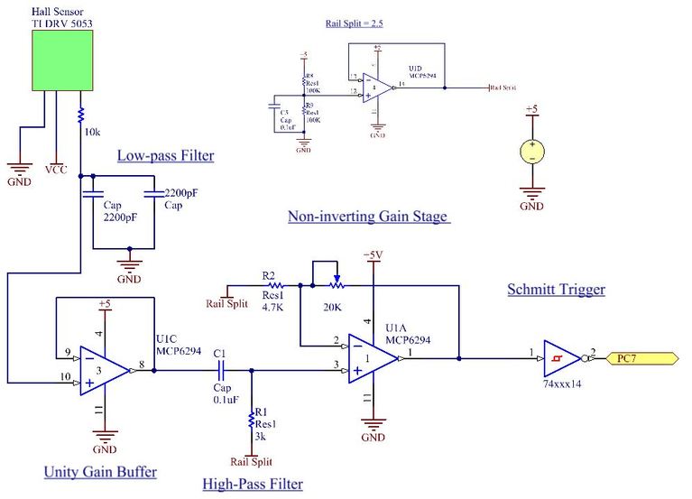
The three different "staging areas" each gave off a distinct magnetic field frequency. In order to sense that we were in the right area and be able to stop there, we used a hall effect sensor with a signal conditioning circuit. The hall effect sensor was able to pick up on the magnetic pulses. We then used a low-pass filter, as per the data sheet, a unity gain buffer, a high pass filter to get rid of noise from the power supply, lights, etc.., and finally an op amp/schmitt trigger combo to amplify the signal and convert it into a digital output for the TIVA. We were then able to determine the frequency of the signal through software. We used a "rail splitter" circuit to ensure our power supply points remained consistent, and to center the signal around 2.5V so that we could use the Schmitt Trigger chip. Incorporating a 20K potentiometer into our gain stage helped with being able to tune the gains in the circuit on the fly (instead of having to resolder a new resistor if changes needed to be made).
| magnetic_field_sensing.pdf |
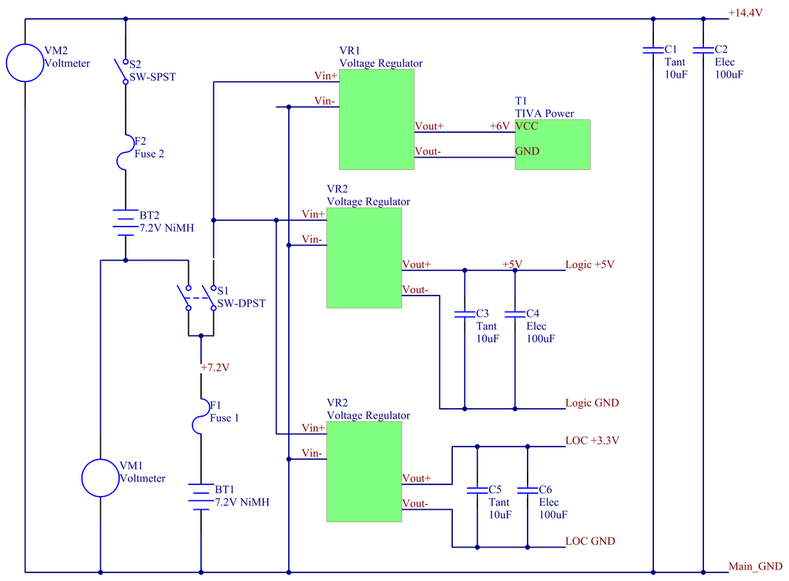
Power Circuit
Easy battery swiching and keeping our power source as noise free as possible were the two main goals for the power circuit below.
Two 7.2V batteries were connected in series to provide an approximately 14.4V source. To protect our circuity from accidental high current, we included a 5 amp fuse after each of the batteries. From one battery's 7.2V, we used switching voltage regulators to provide +6V to efficiently power the TIVA, +5V for logic and sensing, and +3.3V for the LOC.
We designed and implemented the power system to cut power from all circuity when the lower level switch was opened, regardless of the position of the higher voltage switch. However, the circuit allowed the lower battery to be used without the upper one if only the lower switch was closed. This allowed us to test components without worrying if Teddy was going to use the 14.4V to drive off the table.
Two external voltage meters provided clear visual charge status on both batteries.
| power_distribution.pdf |
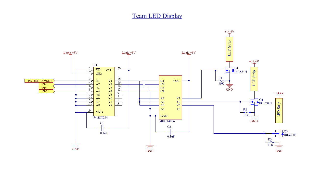
Team LED Status
Between timer inputs and PWM outputs, Tiva alternative outputs started to become scarce as our project neared completion. To reduce unnecessary PWM outputs, we decided to route 1 PWM signal to our RGB LED's. This allowed us to dim all colors evenly while still being able to control each color being on or off individually with normal GPIO outputs. To accomplish this an analog switch was used to route the buffered PWM signal to three power mosfets corresponding to each color LED.
| team_led.pdf |
